Industry News

IC 74192 Synchronous Up/Down Counter: Characteristics, Principles, and Applications

Views : 379
Update time : 2025-12-01 10:26:58
In the realm of digital counting circuits, the 74192 IC stands as a foundational component, renowned for its versatility as a synchronous 4-bit BCD up/down counter. Designed to bridge precision and flexibility, it addresses the core need for reliable decimal counting with bidirectional control—capabilities that have made it a staple in digital meters, timers, and industrial control systems. This exploration delves into its defining characteristics, underlying operational principles, and practical applications, shedding light on why this integrated circuit remains relevant in both legacy and modern digital designs.

74192  

74192 IC Overveiw

The 74192 is a popular TTL synchronous up/down BCD counter, designed for decimal (0-9) counting with bidirectional functionality. It operates synchronously, meaning count transitions occur simultaneously with clock pulses, ensuring precise timing without glitches common in asynchronous counters.
Key features include separate up/down control pins: a HIGH on the up pin triggers incrementing, while a HIGH on the down pin enables decrementing. It includes clear (CLEAR) and load (LOAD) functions—CLEAR resets counts to 0 asynchronously, while LOAD sets preset values synchronously via data inputs.
Carry (CO) and borrow (BO) outputs facilitate cascading multiple 74192s for extended counting ranges (e.g., 0-99 with two ICs). Widely used in digital meters, timers, frequency dividers, and industrial control systems, the 74192 balances versatility and simplicity, making it a staple in digital logic designs.


74192 IC Pinouts


Pin Number Name Function Description
16 Vcc Positive power supply (4.75~5.25 V)
8 GND Ground
14 CLR Clear input (active HIGH, asynchronous operation)
11 LOAD Load control (active LOW, preset data)
5 UP Up-count clock (rising edge triggered)
4 DOWN Down-count clock (rising edge triggered)
15, 1, 10, 9 A, B, C, D Data input pins (preset count starting point)
3, 2, 6, 7 QA, QB, QC, QD Count output pins (QA is LSB, QD is MSB)
12 CO Carry output (outputs pulse when counting up to 9)
13 BO Borrow output (outputs pulse when counting down to 0)

IC 74192 Counter Specifications

Feature Specifications
High-Speed (fMAX)                         54 MHz (Typical) at VCC = 5 V
Low Power Dissipation ICC = 4 µA (Maximum) at TA = 25 °C
High Noise Immunity VNIH = VNIL = 28% VCC (Minimum)
Output Drive Capability Can drive 10 LSTTL (Low Power Schottky TTL) Loads
Symmetrical Output Impedance |IOH| = IOL = 4 mA (MIN.)
Balanced Propagation Delays tPLH = tPHL (Symmetrical)
Wide Operating Voltage Range VCC (OPR) = 2 V to 6 V
Pin and Function Compatibility Compatible with 54/74LS192-193
 

IC 74192 Circuit Diagram


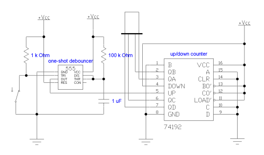
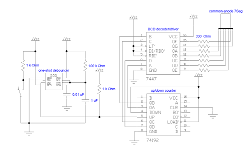
EWB circuit diagram
 

Circuit with Additional Details
 
Two circuits showcase the 74192 synchronous up/down BCD counter, balancing core functionality and user - friendly expansion:

1. Basic Debounced Counting Circuit

Centered on noise - resistant clocking, a mechanical switch paired with a 1 kΩ pull - up resistor triggers a one - shot debouncer (e.g., monostable multivibrator) to eliminate contact bounce. A 100 kΩ + 1 μF RC filter further suppresses noise, delivering “clean” clock signals. The 74192 acts as the core:
Control: UP/DOWN pins drive increment/decrement (synchronous, updating with clock edges); LOAD presets BCD values (via A–D), and CLR asynchronously resets outputs to 0000.
Outputs: QA–QD reflect BCD counts (0000–1001, decimal 0–9); CO/BO enable cascading for multi - digit ranges.
Use Case: Ideal for digital timers/sequential controllers, prioritizing noise - free bidirectional counting.

2. Enhanced Circuit with Display & Decoding

Building on the basic design, this adds visual feedback via a 7447 BCD decoder and seven - segment display:
Input Refinement: The debouncing stage (switch + 1 kΩ + one - shot) is retained, with extra filtering (100 kΩ + 0.01 μF RC, 1 kΩ resistor) for ultra - stable clocking.
74192 Core: Functions identically (counting, preset/clear, BCD output via QA–QD).
Decoding & Display: QA–QD connects to the 7447, which translates BCD to drive a common - anode seven - segment display. 330 Ω resistors limit current; the 7447 includes LT (lamp test, all segments on) and RBI/RBO (ripple blanking for multi - digit zero suppression).
Use Case: A complete system for digital clocks/counters, demonstrating 74192 integration with peripherals for user - friendly interfaces.

Key Takeaways

Both leverage the 74192’s synchronous logic (simultaneous updates). The first focuses on core counting + noise mitigation; the second adds visual feedback via decoding. Together, they illustrate the 74192’s role in building reliable decimal systems—from basic logic to user - facing applications.
 

74192 IC Features

The 74192 IC, a classic synchronous up/down BCD counter, features core characteristics that emphasize flexibility, stability, and ease of use, as detailed below:

Synchronous Counting Operation

All internal flip-flops are driven by the same clock signal. Count transitions occur synchronously with clock pulses, and outputs (QA~QD) update states simultaneously. This eliminates output spikes (glitches) caused by sequential flipping of flip-flops in asynchronous counters, ensuring stable and reliable counting results.

Bidirectional Counting Control

Bidirectional counting is enabled via independent UP (up-count) and DOWN (down-count) dual clock pins:
  1. Up counting: Only the UP pin receives pulses (with the DOWN pin held high), and the count increments by 1 from the current value (0→1→…→9).
  2. Down counting: Only the DOWN pin receives pulses (with the UP pin held high), and the count decrements by 1 from the current value (9→8→…→0).
    The dual-clock design simplifies direction control logic, eliminating the need for additional direction selection signals.

Asynchronous Clear Function

Equipped with a CLR (clear) pin (active high). When CLR is high, regardless of the clock state or counting process, outputs (QA~QD) immediately reset to all zeros (0000). This operation is independent of the clock signal, making it suitable for emergency reset scenarios, with higher priority than counting and loading operations.

Asynchronous Data Loading

Programmable presetting is enabled via the LOAD (load) pin (active low). When LOAD is low, values at data inputs (A~D) are directly loaded to outputs (QA=A, QB=B, QC=C, QD=D), independent of the clock signal (asynchronous operation). This allows quick definition of counting start points (e.g., starting from 5), enhancing counting flexibility.

Carry/Borrow Outputs

Integrated CO (carry) and BO (borrow) output pins automatically indicate counting boundaries:
  1. When counting up to the maximum value 9 (1001), CO outputs a low-level pulse (only when the UP clock is active), indicating "overflow".
  2. When counting down to the minimum value 0 (0000), BO outputs a low-level pulse (only when the DOWN clock is active), indicating "underflow".
    These signals provide direct control for cascading multiple ICs, simplifying expansion designs.

BCD Decimal Counting

Using BCD encoding (8421 code), it has a fixed counting range of 0~9 (0000~1001), unlike binary counters (e.g., 74193) which cover 0~15. This makes it naturally suitable for decimal display and control scenarios (e.g., digital clocks, instrument readings).

Cascading Expansion Capability

Using CO and BO outputs, multiple 74192 ICs can be directly cascaded for multi-digit decimal counting: the CO pin of the previous stage connects to the UP pin of the next stage, and the BO pin of the previous stage connects to the DOWN pin of the next stage. This enables expansion to hundreds (0~99), thousands (0~999), etc., without additional logic circuits.

Wide Operating Conditions

Supports a typical supply voltage (Vcc) of 4.75~5.25V (absolute maximum 7V). Operating temperature ranges from 0~70℃ (commercial grade) to -55~125℃ (military-grade model SN54192), adapting to industrial, laboratory, and other environments. With an output drive capability of 16mA (low level), it can directly drive peripherals such as LEDs and relays.
 
These characteristics make the 74192 a preferred device for accurate and flexible decimal counting in digital systems, especially suitable for scenarios requiring bidirectional counting, custom start points, or cascaded expansion.


74192 IC Function

The 74192 IC is a high-performance synchronous 4-bit BCD (decimal) up/down counter. Its core function is to achieve precise bidirectional decimal counting under clock signal control, with flexible control features to adapt to diverse digital system requirements. Its specific functions are as follows:
Synchronous Decimal Counting (0~9 Cycle)
As a BCD counter, it adopts 8421 encoding, naturally adapting to decimal counting logic, with a fixed counting range of 0 (0000) to 9 (1001). All internal flip-flops are synchronously driven by the same clock signal, ensuring count transitions (e.g., 3→4, 8→9) occur synchronously with the clock pulse edge (rising edge). Output pins (QA~QD) update states simultaneously, avoiding output glitches in asynchronous counters and ensuring stable counting results.
Bidirectional Counting Control (Up/Down Switching)
Bidirectional counting switching is realized via independent UP (up-count clock) and DOWN (down-count clock) pins, requiring no additional direction control signals:
  1. Up counting: When the DOWN pin is held at high level and continuous pulses are input to the UP pin, the counter increments sequentially from the current value (e.g., 5→6→7→…→9, then cycles back to 0).
  2. Down counting: When the UP pin is held at high level and continuous pulses are input to the DOWN pin, the counter decrements sequentially from the current value (e.g., 5→4→3→…→0, then cycles back to 9).
Asynchronous Clear and Preset Load (Flexible Initialization)
  1. Asynchronous clear: Via the CLR (clear) pin (active HIGH), the counter outputs can be forced to all zeros (0000) at any time, with the operation independent of the clock signal (no need to wait for clock pulses). This is suitable for system reset or emergency clear scenarios.
  2. Asynchronous load: Via the LOAD (load) pin (active LOW), preset values from data input pins (A~D) (e.g., 0101, i.e., decimal 5) can be directly loaded to output pins (QA~QD) without relying on the clock, quickly defining the counting start point (e.g., starting up/down counting from 5).
Carry/Borrow Outputs (Support for Cascading Expansion)
Integrated CO (carry output) and BO (borrow output) signals automatically mark count boundaries, providing direct control for multi-chip cascading:
  1. When counting up to the maximum value 9 (1001), the CO pin outputs a low-level pulse (only when the UP clock is active), indicating "overflow," which can drive the UP pin of the next-stage counter to enable increment of the higher digit.
  2. When counting down to the minimum value 0 (0000), the BO pin outputs a low-level pulse (only when the DOWN clock is active), indicating "underflow," which can drive the DOWN pin of the next-stage counter to enable decrement of the higher digit.
Through cascading, it can be expanded into multi-digit decimal counters (e.g., 2 chips for 0~99 counting, 3 chips for 0~999 counting, etc.).
In summary, the core function of the 74192 is to provide stable and controllable decimal counting capability for digital systems through synchronous operation, bidirectional counting, flexible initialization, and cascading expansion. It is widely used in scenarios such as digital meters, timers, and frequency dividers.


74192 IC Real Applications

As a synchronous up/down BCD counter, the 74192 IC is widely used in scenarios requiring decimal counting, bidirectional control, or flexible expansion. Its key applications include:
Digital display counting systems: Such as electronic scales and piece counters. They utilize the bidirectional counting function to count item increments (UP for addition) and decrements (DOWN for subtraction), with synchronous output ensuring no display jumps.
Countdown devices: Including traffic lights and oven timers. By presetting initial time via LOAD and cooperating with down counting (DOWN), they intuitively display remaining time and trigger an alarm when counting down to 0.
Decimal frequency dividers: In communication or measurement equipment, they divide high-frequency signals (e.g., 100Hz) into low-frequency ones (e.g., 10Hz). Using the carry output (CO) to achieve 10x frequency division, they adapt to decimal logic.
Bidirectional position tracking: For elevator floor counting or conveyor belt displacement counting, forward pulses are connected to UP and reverse pulses to DOWN, reflecting position changes in real time. Synchronous operation avoids counting errors.
Custom range counting: In production line batch packaging (e.g., groups of 5), non-0~9 cycles are achieved via preset values and logical feedback, simplifying designs for specific counting requirements.


74192 Truth Table

The 74192 is a synchronous up/down BCD counter. Its Truth Table describes the correspondence between input signals and output states. Core inputs include clear (CLR), load (LOAD), up-count clock (UP), down-count clock (DOWN), and data inputs (A/B/C/D); outputs include BCD count outputs (QA/QB/QC/QD), carry (CO), and borrow (BO).

74192 Truth Table (Simplified Version)

Input Signals Function Description Output States          
CLR LOAD UP DOWN A/B/C/D QA/QB/QC/QD CO (Carry) BO (Borrow)
H × × × × 0000 (Clear) H (Invalid) H (Invalid)
L L × × A/B/C/D A/B/C/D (Load) H H
L H H × Increment count (+1) Outputs L pulse when counting up to 9 H
L H H × Decrement count (-1)         H Outputs L pulse when counting down to 0
L H H H × Hold current value H H

Symbol Explanations:

  1. H: High level (valid/invalid depending on function); L: Low level;
  2. ×: Don't care (any state, no impact on results);
  3. ↓: Clock pulse falling edge (effective edge for triggering counting);
  4. CO (Carry Output): Outputs a low-level pulse only when counting up to 9 (1001) and the UP clock is active (drives higher-digit increment);
  5. BO (Borrow Output): Outputs a low-level pulse only when counting down to 0 (0000) and the DOWN clock is active (drives higher-digit decrement).

Summary of Core Logic:

  1. Clear (CLR) has the highest priority: When CLR=H, regardless of other inputs, the output is forced to 0000;
  2. Load (LOAD) is next: When CLR=L and LOAD=L, the output is directly equal to the data input A/B/C/D (asynchronous load);
  3. Counting function: When CLR=L and LOAD=H, increment counting is triggered by the UP falling edge, and decrement counting by the DOWN falling edge;
  4. Hold state: The output remains at the current value when there is no effective clock pulse.

IC 74192 Related Parts

Part Number Counter Type Reset Type
74160 4-bit Decade Counter Asynchronous Reset
74162 4-bit Decade Counter Synchronous Reset
74190 4-bit Up/Down Decade Counter Asynchronous Reset
74192 4-bit Up/Down Decade Counter Asynchronous Reset
 

74192 IC Manufacturer

The 74192, a synchronous 4-bit BCD up/down counter, has been made by multiple firms. Original manufacturers include Texas Instruments (TI), with variants like SN74192N now mostly discontinued; National Semiconductor, whose production likely ceased after TI’s 2011 acquisition; and Fairchild Semiconductor, which stopped post-2016 acquisition by ON Semiconductor.
STMicroelectronics remains active, offering TTL-compatible high-speed CMOS variants like M54/74HC192 with ongoing support. Currently, distributors like Rochester Electronics and Jameco provide legacy or remanufactured parts.
For modern use, CMOS alternatives such as 74HC192/74HCT192 (from ST, Nexperia) are preferred, with lower power and broader voltage compatibility. Note that original TTL versions are obsolete; ensure voltage matching (5V TTL vs. 2–6V HC/HCT).


74192 IC Category-TTL synchronous up/down BCD counter

TTL synchronous up/down BCD counters are pivotal in digital systems requiring decimal counting with bidirectional control. They operate synchronously, ensuring all outputs update simultaneously with clock pulses, eliminating glitches common in asynchronous designs. Supporting both increment (0-9) and decrement (9-0) operations via separate clock inputs, they seamlessly integrate with decimal-centric applications like digital displays and timers.
Their BCD encoding aligns with human-readable decimal systems, simplifying interfacing with seven-segment displays. Among these, the 74192 IC stands as a classic example, embodying these traits with added features like asynchronous clear/load and carry/borrow outputs for cascading. It remains a staple in designs needing reliable, flexible decimal counting, bridging functional precision with practical usability.


74192 IC Datasheet

https://www.ti.com/lit/ds/symlink/sn54192.pdf?ts=1754250724798&ref_url=https%253A%252F%252Fwww.ti.com%252Flit%252Fgpn%252FSN54192


Conclusion

From its synchronous operation that eliminates output glitches to its bidirectional counting and cascading capabilities, the 74192 IC encapsulates the balance of simplicity and functionality critical for decimal counting systems. Its adaptability—whether in digital displays, countdown timers, or frequency dividers—underscores its enduring value in electronics. While modern alternatives offer advanced features, the 74192’s robust design and straightforward logic continue to make it a go-to choice for engineers seeking reliable, cost-effective counting solutions.
 
Related News
Read More >>
LDK220 LDO Voltage Regulators Specifications, Features, Pinout, and Applications LDK220 LDO Voltage Regulators Specifications, Features, Pinout, and Applications
Feb .02.2026
The LDK220 series of low-dropout linear regulators (LDOs) is a high-performance device designed specifically for low-power consumption and high-precision voltage regulation, widely used in scenarios such as consumer electronics, industrial control, and po
Xilinx Spartan®-7 FPGA Family: A High-Performance and Energy-Efficient Solution for Mid-Range FPGAs Xilinx Spartan®-7 FPGA Family: A High-Performance and Energy-Efficient Solution for Mid-Range FPGAs
Jan .20.2026
Xilinx Spartan®-7 FPGA Family stands as a defining solution in the mid-range FPGA landscape, blending high performance, energy efficiency, and cost-effectiveness to redefine versatility for industrial, IoT, and consumer electronics applications. Built on
Altera FLEX Series: Architecture, Innovation, and Application Across Four Generations Altera FLEX Series: Architecture, Innovation, and Application Across Four Generations
Jan .07.2026
The Altera FLEX series was more than a lineup of FPGAs—it was a blueprint for how programmable logic devices could evolve to meet diverse market needs. The FLEX 8000 laid the architectural groundwork, the FLEX 10K redefined functionality with embedded mem
LM4765 vs. LM4766: A Comprehensive Comparison of Dual-Channel Audio Power Amplifiers LM4765 vs. LM4766: A Comprehensive Comparison of Dual-Channel Audio Power Amplifiers
Dec .16.2025
Among TI standout offerings, the LM4765 and LM4766 are dual-channel amplifiers designed to cater to diverse audio needs—from compact setups to high-fidelity systems. While sharing the same product lineage, these chips differ significantly in power output,