In the field of electronic technology, multivibrators, as circuits capable of autonomously generating periodic pulse signals, are core components in digital systems, timing control, and signal processing. Through the synergistic effect of positive feedback mechanisms and RC timing networks, they achieve periodic switching of circuit states, outputting non-sinusoidal waveforms such as square waves and rectangular waves, and providing basic timing signals for various electronic devices. This article will systematically sort out the circuit types, working principles, and typical applications of multivibrators, revealing their key role in modern electronic technology.
I. Core Principles and Basic Characteristics of Multivibrators
A multivibrator is essentially an electronic circuit that achieves self-oscillation through positive feedback. Its core components include: active devices capable of rapid state switching (such as transistors, operational amplifiers, logic gates, or 555 timers), capacitors (C) for energy storage and release, resistors (R) for controlling charge/discharge rates, and coupling networks that form positive feedback.
The operation of the circuit revolves around "state switching": when power is applied, the active devices alternately enter conduction and cutoff states under the charge/discharge action of the RC network. Small changes are amplified through positive feedback, resulting in stable periodic pulse output. The frequency (f) and pulse width (t) of the output waveform are determined by the RC time constant (τ=R×C), making it a controllable "electronic clock."
Compared to sine wave oscillators, multivibrators have distinct features: their output waveforms contain rich harmonics (hence the name "multivibrator"), making them more suitable for logic level switching in digital circuits; their structure is simple, requiring no resonant circuits (such as inductors or crystals), resulting in lower costs; and their frequency is flexibly adjustable, with a wide range of frequency tuning achievable by changing R or C parameters.
II. Circuit Types and Operating Mechanisms of Multivibrators
Based on the number of stable states, multivibrators can be divided into three main categories: astable multivibrators, monostable multivibrators, and bistable multivibrators. Different types of circuits vary significantly in state switching methods, triggering conditions, and output characteristics, making them suitable for different scenarios.
1. Astable Multivibrator (Free-Running Oscillator)
An astable multivibrator is a self-oscillating circuit with no stable states. After power-up, it continuously switches between two transient states without external triggering, outputting a continuous square wave. Its core is to control state inversion through the charge/discharge process of the RC network. Typical circuits include transistor cross-coupled circuits, 555 timer circuits, and logic gate oscillators.
Typical Circuit: 555 Timer Astable Oscillator
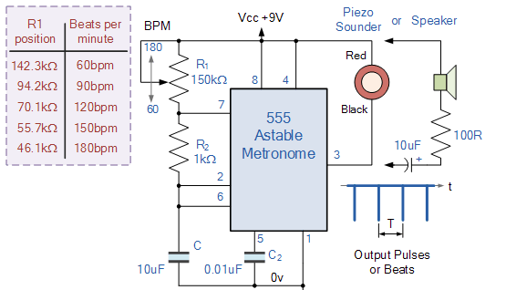 555 Timer Astable Oscillator
2. Monostable Multivibrator (One-Shot Trigger)
A monostable multivibrator has one stable state and one transient state. It enters the transient state only under the action of an external trigger signal (such as a pulse or level transition), remains there for a fixed time, and then automatically returns to the stable state, outputting a single pulse. The pulse width is precisely controlled by the RC time constant, making it the core of an "electronic timer."
Typical Circuit: 555 Timer Monostable Circuit
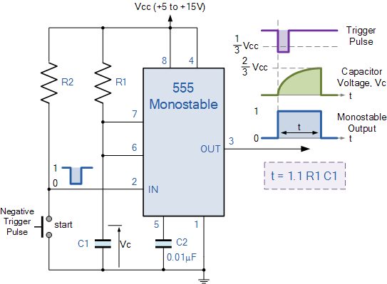 555 Timer Monostable Circuit
Let's dig into this 555 timer monostable circuit. First off, the 555 chip is the star here, right at the center of everything. It's got these internal bits—comparators, a flip - flop, and output drivers—that work in tandem to make this monostable magic happen.
We've got resistors R1 and R2. R1, along with capacitor C1, is super important for setting the pulse width. You see, in a monostable circuit, once triggered, it spits out a single pulse whose width is all about the time constant of R1 and C1. And R2? Well, it's there to keep the voltage at pin 6 (which is connected to the threshold input) at a steady level when the circuit is in its stable state.
Then there's capacitor C1. It's the timing capacitor. When the circuit gets triggered, C1 starts charging through R1. How fast it charges, and when it reaches certain voltage levels, determines how long the output pulse lasts. And C2 (0.01μF) is a decoupling capacitor, filtering out any high - frequency noise from the power supply so the 555 timer can stay nice and stable.
The power supply, Vcc, can range from +5 to +15V, which is perfect for the 555 timer's typical operating voltage needs. This gives the circuit the juice it needs to function.
Now, let's talk about how it works. In the stable state, the output (pin 3) is low. Capacitor C1 is discharged, sitting at 0V. Then, along comes a negative trigger pulse at pin 2. When that trigger pulse drops below 1/3 Vcc, it kicks the circuit into action. The internal flip - flop flips, and the output goes high. Now, C1 starts charging through R1. The voltage across C1, Vc, climbs up.
This charging keeps going until Vc hits 2/3 Vcc. Once it does, the internal comparator kicks in, resetting the flip - flop. The output then drops back to low, and C1 discharges through the internal discharge path of the 555 timer. The duration of that high - output pulse, t, is given by the formula t = 1.1 R1 C1. So, you can adjust R1 or C1 to make that pulse width longer or shorter, depending on what you need.
This monostable circuit is really handy. You can use it for things like creating a timed delay—maybe to turn on a relay for a specific amount of time after a trigger. Or for pulse shaping, taking a messy input pulse and turning it into a nice, clean, fixed - width output pulse. It's amazing how these simple components—the 555 timer, a couple of resistors, and capacitors—can work together to do such useful things in electronics projects.
3. Bistable Multivibrator (Flip-Flop)
A bistable multivibrator has two stable states and can switch between "0" and "1" states via external trigger signals. Once a state is determined, it remains stable without energy input, serving as the basic unit for storing information in digital circuits (also called a "flip-flop").
Typical Circuit: SR Flip-Flop (Based on NAND Gates)
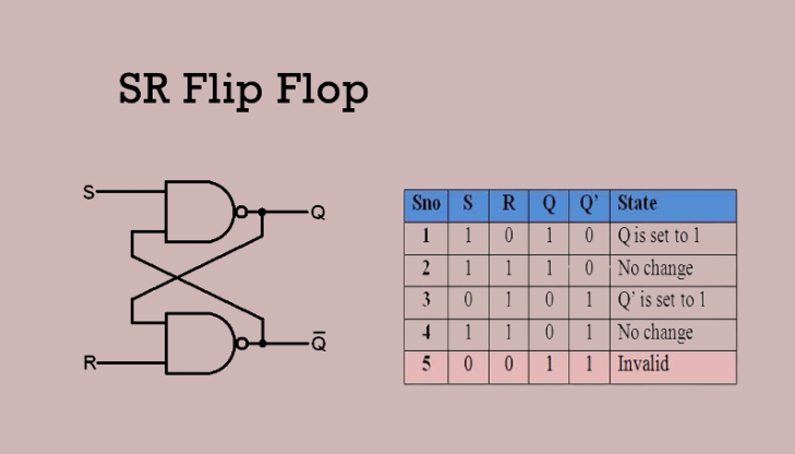 SR Flip-Flop (Based on NAND Gates)
| Inputs (S, R) |
Outputs (Q, (overlineQ |
State Description |
| 1, 0 |
Q = 1, -Q = 0 |
Set state (Q is set to 1) |
| 1, 1 |
No change in Q and -Q |
No - change state |
| 0, 1 |
Q = 0, -Q= 1 |
Reset state -Q is set to 1) |
| 0, 0 |
Q = 1, -Q = 1 |
Invalid state (violates complementarity) |
Derived Types:
-
D Flip-Flop: The D flip-flop has one input, one output, and one clock frequency input. When the clock frequency changes from 0 to 1, the output value will be equal to the input value. Such flip-flops can be used to prevent errors caused by noise and can increase the amount of data processed through the pipeline.
The truth table is as follows:
| D |
CK |
Q |
Qnext |
| 0 |
↑ |
X |
0 |
| 1 |
↑ |
X |
1 |
| X |
0 |
0 |
0 |
| X |
0 |
1 |
1 |
-
JK Flip-Flop: Dual-input J and K, supporting set, reset, and toggle functions (state flips when J=K=1), suitable for counters.
-
T Flip-Flop: The state toggles when input T=1 and remains when T=0, used for frequency division.
III. Typical Application Scenarios of Multivibrators
Multivibrators are widely used in consumer electronics, industrial control, digital communication, and other fields, with their core value lying in providing controllable pulse signals or state storage functions. The following are typical application categories:
1. Timing and Delay Control
- Household Appliance Timers: The timing functions of microwave ovens and washing machines rely on monostable multivibrators. The working time is set via RC parameters, and a relay is triggered to power off when the time elapses.
- Automotive Turn Signals: Astable multivibrators generate 1-2Hz square waves to control alternating flashing of turn signals (frequency calibrated by the RC network to meet traffic regulations).
- Circuit Startup Delay: After power-on, a monostable oscillator delays the startup of sensitive circuits (such as audio amplifiers) by a few seconds to avoid damage from inrush current.
2. Digital System Clocks and Synchronization
- Microcontroller Clocks: In simple embedded systems, astable oscillators (such as RC oscillators based on logic gates) provide reference clocks for microcontrollers (replacing high-precision crystals to reduce costs).
- Counters and Frequency Dividers: Cascaded bistable flip-flops form binary counters to divide high-frequency clocks (e.g., dividing a 1MHz clock to 1Hz for electronic watch timing).
- Data Transmission Synchronization: In communication protocols such as UART and SPI, clock signals generated by astable oscillators ensure alignment of signals between transmitters and receivers, preventing data misalignment.
3. Signal Processing and Modulation
- Pulse Width Modulation (PWM): Astable oscillators generate square waves with adjustable duty cycles, controlling load power by changing the high-level duration (e.g., LED brightness adjustment, DC motor speed control).
- Sensor Signal Shaping: Irregular pulses output by infrared sensors and photoelectric switches are converted into fixed-width standard signals by monostable oscillators, facilitating recognition by microcontrollers (e.g., infrared induction signal processing for automatic doors).
- Audio Signal Generation: Astable oscillators generate 20Hz-20kHz square waves, which can be used as simple audio signals after filtering (e.g., electronic buzzers, toy sound effects).
4. State Storage and Control
- Button Lock Circuits: Bistable flip-flops are used to lock the start/stop state of equipment (e.g., emergency stop buttons on industrial machine tools, which remain in a power-off state after being pressed and require reset to restart).
- Digital Memory: Multiple D flip-flops are cascaded to form registers for temporary data storage (e.g., accumulators and caches in microprocessors).
- Logic Control: Shift registers composed of JK flip-flops can 实现 serial-to-parallel data conversion (e.g., converting 8-bit serial input data to parallel output to drive 7-segment displays).
5. Industrial and Security Applications
- Alarm Systems: Astable oscillators drive piezoelectric buzzers to generate continuous alarm sounds (e.g., smoke alarms, anti-theft systems), with monostable oscillators controlling the alarm duration.
- Motor Speed Feedback: Pulse signals output by Hall sensors on motor shafts are shaped by bistable flip-flops and input to counters to calculate speed (real-time monitoring of motor operating status).
- Automatic Detection Equipment: Pulses generated by astable oscillators trigger laser sensors, and object distances are calculated by measuring the time difference of reflected signals (e.g., material positioning on production lines).
IV. Selection and Design Considerations
In practical applications, the following points should be noted when selecting and designing multivibrators:
- Frequency Stability: For scenarios requiring high precision (such as clocks and communication), prioritize oscillators with crystals (replacing RC oscillators); low-cost scenarios can use 555 timers (with a frequency error of approximately 5%-10%).
- Power Consumption Control: Battery-powered devices (such as remote controls and IoT sensors) should use oscillators composed of CMOS logic gates, which have extremely low static power consumption (μA level).
- Environmental Adaptability: In high-temperature and high-humidity environments, industrial-grade components (such as military-grade 555 timers) should be selected, and RC parameters should be used to compensate for temperature drift (e.g., using negative temperature coefficient resistors).
- Anti-Interference Design: In strong electromagnetic environments (such as near motors), circuits need to add filter capacitors and shielding layers to prevent false triggering of monostable or bistable circuits by external noise.
Multivibrators are fundamental units in electronic circuits for generating pulse signals and achieving state control. Their three core types—astable, monostable, and bistable—correspond to the three main functions of "continuous oscillation," "single-shot triggering," and "state storage," respectively. From simple LED flashing circuits to complex microprocessor systems, multivibrators find applications everywhere. Understanding their working principles and key selection points is of great significance for electronic design, troubleshooting, and innovative applications. With the development of integrated circuit technology, multivibrators are gradually being integrated into SoCs (System-on-Chips). However, classic circuits based on discrete components or 555 timers, due to their low cost and ease of implementation, will still play an important role in electronic engineering.
WlS Electronic keeps a large stock of Multivibrators Circuit electronic components, high-performance and versatile solutions for reliable pulse generation and timing control in various electronic systems. Sourced directly from leading manufacturers, all components are guaranteed genuine and brand-new, with strict quality assurance processes to ensure stable performance in industrial control, consumer electronics, automotive electronics, and other applications. For technical support, detailed datasheets and application notes (such as astable oscillator designs for clock signal generation, monostable circuit solutions for timing delays) are available upon request.
Quick Quote & Support:
To get a quote, please fill in the quantity, your name, and email in the form on the right. Our sales team will reply within 12 hours. For urgent needs:
Contact us via live chat support.
Email us at: SALES@WLSCHIP.COM